Barrel Making Machinery
Stave and Barrel manufacturing equipment from Anthon GmbH with over a century of experience in this market. Automate production while maintaining the heritage processes of a traditional cooperage!
Type of Barrel:
For Aging Whiskey
The Line is designed for standard Barrel size of: 225

Barrel Making Specifications
Anthon Barrel Making
| Bulge diameter: | ~ 700 | mm |
|---|---|---|
| Head diameter: | ~ 550 | mm |
| Barrel height: | ~ 950 | mm |
| Stave thickness: | 25 – 27 | mm |
| Bunge hole ø: | 50 | mm |
| Hoops: | 6 | pcs. |
Timber Used:
Oak, Chestnut, Pecan, Maple and Acacia etc.
For the 225 liter Barrel size we will equip the machines with one set of necessary tools. For other Barrel size, tools need to be purchased separately.
Standard barrels size: minimum volume is ~100-liter, maximum volume ~1.000 liter suitable for our barrel making equipment.
The operating Voltage for each machine of the line is:
480 Volt; 60 Hertz; 3 Phases.
Required production per day in an 8 hour shift:
Stave Dimensions: (all is depending on the machine type)
Stave Dimensions
| Max head Width: | 60 mm | Min Width: | 40 mm |
|---|---|---|---|
| Max Thickness: | 35 mm | Min Thickness: | 22 mm |
| Max Length: | 1.300 - 1800 mm | Min Length: | 600 mm |
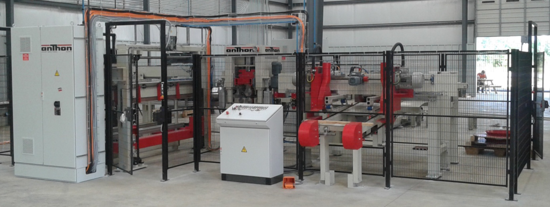
Stave cutting DAV, Stave backing- & hollowing machine DH
Function
The DAV/DH serves for cutting and backing–and hollowing of staves.
Both stave ends are cut off at the same time. The backing and- hollowing tools process one side of the
stave concave and the other convex.
Mechanical structure:
- The machine consists of a robust steel frame construction
- Feeding into the saw with chain feed
- 2 movable circular saws, one per side
- Push feeder into the backing-and hollowing tool
- 1 hollowing-and backing tool from bottom and top side
- Capacity: approx. 8-10 staves/minute
Working method:
- The stave is put crosswise onto two chains with dogs which run in parallel to each other.
- When the chains run forward the stave is transported under two pressure devices where it is
clamped fast, to keep it in position during sawing. - At the right- and left-hand side is always one adjustable saw unit. The saw units can be adjusted
motor driven on linear guide systems. - A transfer pusher transports the shortened staves in front of the backing- and hollowing machine.
- A push feeder pushes the stave through two spring loaded centering devices in front of the
pressure roll of the backing- and hollowing machine. The pressure rolls of the backing- and
hollowing unit are driven and the surface is knurled. - The stave is pulled into the backing- and hollowing machine by the pressure rolls and processed
in one operation. - The top tool is convex, and hollows the inside of the stave. The bottom tool is concave and
performs the backing process at the outside of the stave. - The top tool can hollow the stave with or without head.
- If backing- and hollowing „with head „is selected, the hollowing tool remains lifted during the
first centimeters, when the stave is under the tool and then the tool lowers and before the stave
has run completely through the backing– and hollowing tool it is raised again and also does not
back- and hollow the last centimeters on the other side of the stave. This keeps the head more
robust. - If „without head “is selected, the backing-and hollowing tool is lowered over the complete stave
length and the material becomes thinner. - The top part of the tool (convex) can be lifted pneumatically 200 mm over 4 lifting columns.
Thus, allowing to remove the tools easily. - With a hand wheel, which is located at the top part of the backing- and hollowing machine, the
stave thickness can be adjusted. - At the end of the machine the staves are collected on tiltable bars till a limit switch. When the
bars are full with staves they tilt away and the staves are falling onto a frame for collecting. The
fame cam be moved down and the staves can be transported away.
Technical Data: DAV/DH
| Working range: | max. stave length | 1.500 mm | |
|---|---|---|---|
| min. stave length | 850 mm | ||
| min. stave width | 40 mm | ||
| min. stave width | 160 mm | ||
| max. stave thickness | 2 mm | ||
| min. stave thickness | 20 mm | ||
| Capacity | Stave length < 900 mm | 10 cycles | |
| Stave length > 900 mm | 8 - 9 cycles | ||
| Drive power | Stave cut saws | 2 x 4,0 kW | |
| Stave adjustment | 0,25 kW | ||
| Stave / chain conv. | 0,75 kW | frequency controlled | |
| Stave push-feeder | 0,75 kW | frequency controlled | |
| Stave backing- and hollowing tool | 2 x 5,5 kW | ||
| Feed rolls top | 0,75 kW | frequency controlled | |
| Feed rolls bottom | 0,75 kW | frequency controlled | |
| Installed power | 24,5 kW | ||
| Extraction data | Extraction studs | 2x Ø 160 mm | |
| 2x Ø 120 mm | |||
| Air speed | |||
| Air consumption | |||
| Vacuum in extraction line | |||
| Compressed air | Consumption at 6 bars | 80 l/min | 480 Nl/min uncompressed air |
| Tools | Stave cut saw | 2x Ø 300 x 4,4 x60 | z = 60 TF |
| Profile milling cutter concave bottom | DA = 120 mm x 200 lg | Radius acc. to barrel- Ø | |
| Profile milling cutter convex top | DA = 120 mm x 200 lg | Radius acc. to barrel- Ø | |
| Control voltage | 24 V GS | ||
| Control | S7 | Siemens |
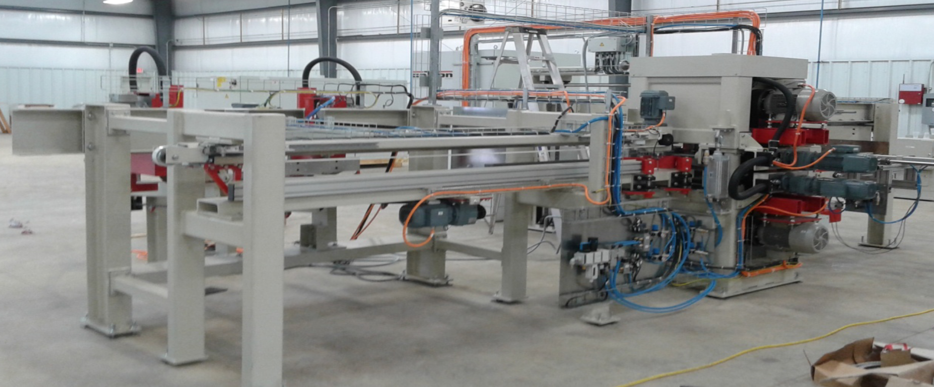
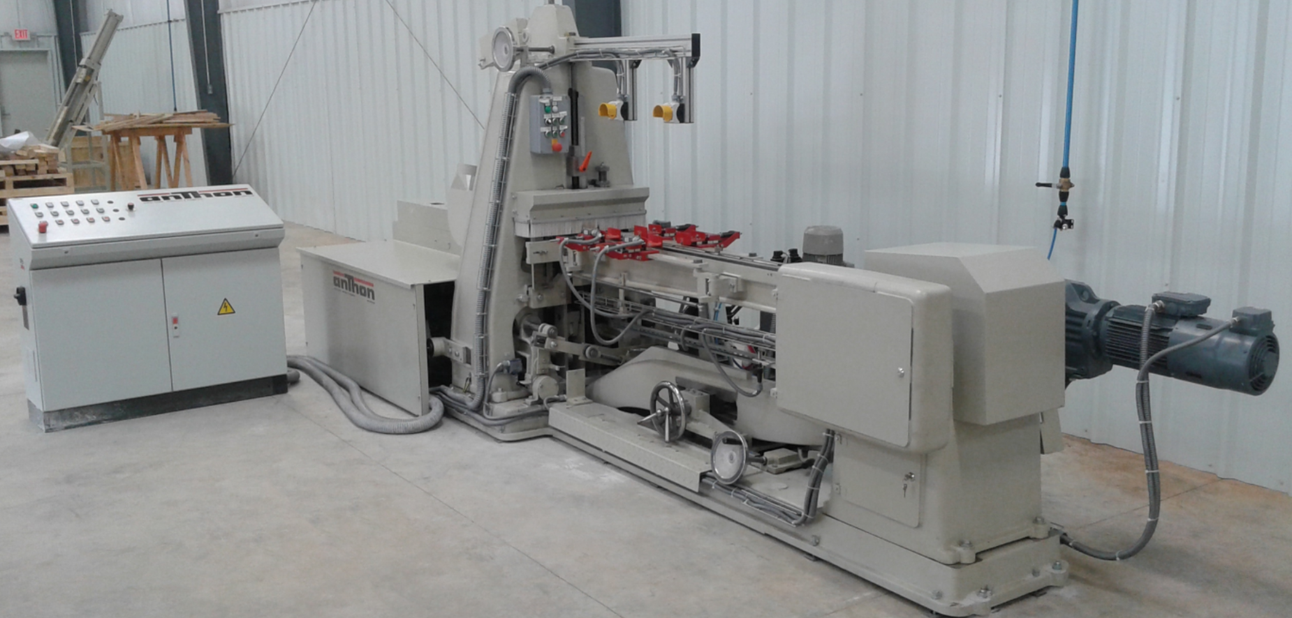
Stave jointer, Model DFV 180
Function:
The DFV 180 serves as jointing sawn and split, also somewhat crooked and twisted barrel staves with a minimum head width of 38 mm and a maximum bulge of 160 mm, up to a thickness of 50 mm and 1.800 mm in length.
Capacity: approx. 10 staves/minute
Accessories:
- 1 Set of exchangeable dogs,
- 1 Set of change gear wheels,
- 1 cam for one specific barrel size
Mechanical structure:
- The DFV 180 is a heavy-duty iron structure and consists of the following:
- Base frame
- Balancing beam
- Guide track with feed chain
- Centering device
- Scissor adjustment device
- Device for bulge adjustment by hand wheel
- Template
- 2x Milling cutters
- Pressure devices
Working method:
- The stave is put on a feed chain with dogs
- By pressing two push buttons simultaneously the feed chain is started.
The chain feed can be adjusted infinitely over a frequency converter. - The stave is centred on the chain by 4 pressure loaded scanning devices.
- The stave runs through two inclined milling cutters, which close and open while the stave runs
through, giving the stave its specific shape. - The stave is pressed onto the chain by a pressure device.
- The guided move of the milling cutters is affected by a template running on a scan roll and which
is attached to a balancing beam.
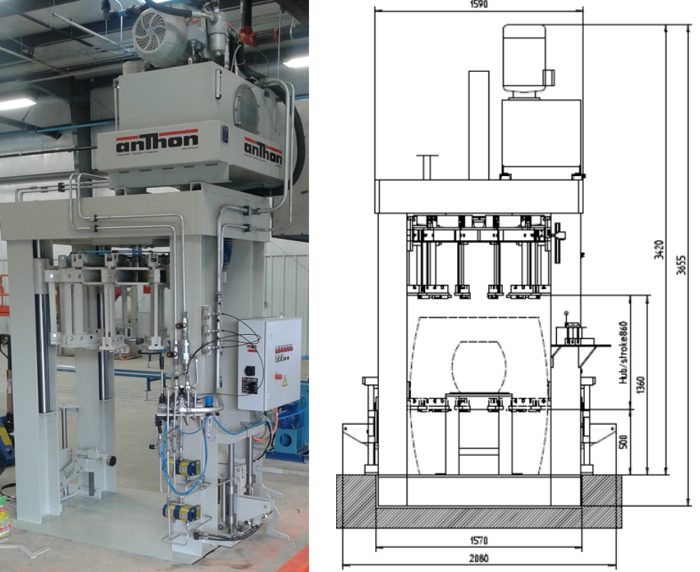
Hydraulic Hoop trussing machine, Model RTH
Function:
The one-sided hydraulic hoop trussing machine, model RTH, serves for driving and re-driving band iron hoops onto barrels of a head diameter from 540 – 800 mm and a height of 400 – 1.100 mm.
Automatic crozing machine, Model KRZE
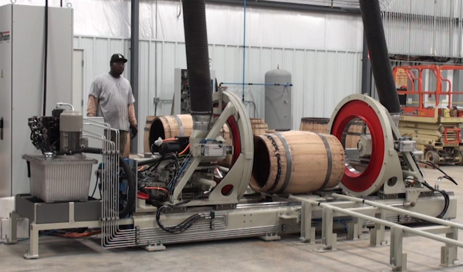
Function:
The crozing machine is designed to mill the croze and for chamfering and cleaning of the barrel ends.
utomatic crozing machine, Model KRZE
| Barrel head diameter | min. 360 mm | max. 800 mm |
|---|---|---|
| Bulge diameter | min. 415 mm | max. 900 mm |
| Barrel height | min. 500 mm | max. 1.350 mm |
Motor driven adjustable cross slide for the milling cutters, infinitely adjustable drive for barrel turning. Barrel clamping and adjustment of the left-hand clamping ring is driven pneumatically.
Capacity: approx. 90 seconds/barrel with automatic feeding and removal
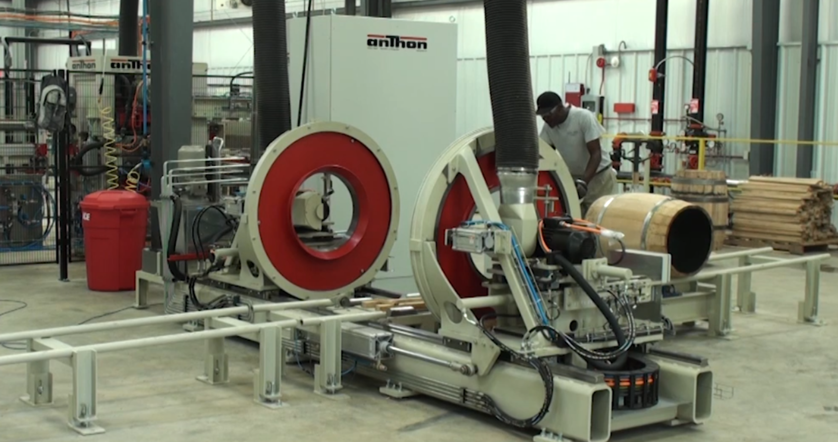
Mechanical structure:
- The base frame of the machine consists of robust length- and cross beams made of steel.
- On the longitudinal beams exchangeable linear guides are mounted for guiding the clamping
slides (right- and left-hand side). - Between the longitudinal beams a motor driven barrel lifting device with a pneumatic eject device is installed.
- On the clamping slides turning-supports and the gear rim housings are mounted for barrel turning.
- On the turning-supports the cross- and length slides are mounted and, on the length, slides are the milling motors. These slides are individually positioned over a hydraulic unit.
- One clamping ring side is traversed pneumatically.
- The zero side is traversed motor driven.
Tool change:
The milling cutters are equipped with a quick clamping system allowing a rapid exchange of the tools.
Working method:
- The operator puts the barrels on two rails which are in parallel to each other and slightly inclined towards the machine.
- The first barrel rolls onto the lifting device between the clamping rings.
- A lowerable stop retains the remaining barrels on the rails.
- The lifting device raises the barrel into a determined position.
- One clamping ring side travels motor driven into the input position (depending on the barrel size).
- The clamping rings close and clamp the barrel. Clamping of the opposite clamping ring side is
pneumatically. The pressure is switched off by a pressure switch. - The lifting device lowers and the barrel turning device is started.
- The milling cutters are started and approach forward to the barrel ends to the inner side of the barrel. The position is detected by cam switch.
- When the milling cutters have reached the input position, they approach crosswise towards
the barrel ends and mill the croze. - After the actual crozing process the barrel still makes 1 or 2 more revolutions, for cleaning the groove of the croze.
- Next the milling cutters approach crosswise towards the center of the barrel and then move reverse out of the barrel.
- The barrel turning is stopped and the lifting device travels under the barrel again.
- The clamping rings open and the barrel is ejected onto the outfeed rails with the pneumatic eject device, where it is removed manually by the operator.
- The stop at the infeed lowers and the next barrel rolls between the clamping rings for crozing.
- This process is repeated until the input number of barrels has been crozed.
Accessories:
In the machine price 1 set of clamping rings for one specific barrel size and one set of milling cutters are included.
Further clamping rings and milling tools for different barrel sizes are charged extra.
Clamping Ring set: 7.000€
Tool set: 5.000€
Technical Data: KRZE
| Working range: | Barrel height max. | 1.350 mm | Feeding automatic |
|---|---|---|---|
| Barrel height min. | 750 mm | Feeding automatic | |
| Bulge diameter | 415 - 900 mm | ||
| Head diameter | 360 - 800 mm | ||
| Capacity | per barrel | 90 sec. | Feeding automatic |
| per barrel | 180 sec. | Feeding manually | |
| Barrel clamping pneum. adjustment | Motor driven | 1 x 0,75 kW | |
| Drive power | Milling cutter right | 7 kW at 100 Hz | frequency controlled |
| Milling cutter left | 7 kW at 100 Hz | frequency controlled | |
| Cross slide, Milling slide, Barrel raising | hydraulically | 3 kW | |
| Barrel turning | Motor driven | 2 x 1.5 kW | frequency controlled |
| Extraction data | Extraction studs | 2x Ø 160 mm | |
| Air speed | 30 m/s | ||
| Air consumption | 1.2m³/s | 4.320m³/h | |
| Vacuum in extraction line | 650 Pa | ||
| Compressed air | Consumption at 6 bars | 28l /cycle (168Nl/cycle) | Feeding automatically |
| Consumption at 6 bars | 18l /cycle (108 Nl/cycle) | Feeding manually | |
| Tools | Milling cutter left | ||
| Milling cutter right | |||
| Weight | |||
| Dimensions | length: Width: Height: | 4.000 mm 1.600 mm 1.400 mm | |
| Infeed rail | 5.000 mm | #NAME? | |
| Installed power | |||
| Control voltage | 24 V GS | ||
| Control | S7 | Siemens |
Barrel base trimmer, Model BRX
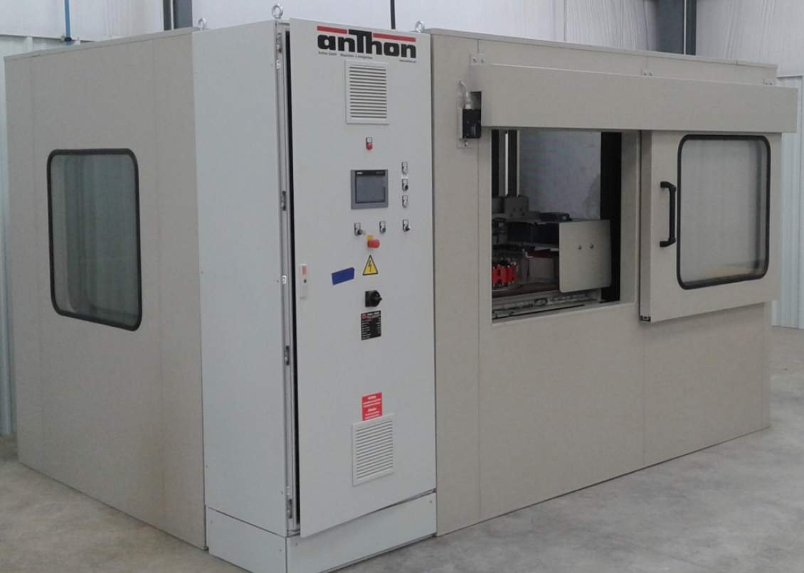
Function:
The barrel base trimmer, model BRX, serves for rounding and chamfering of barrel bases.
- Mechanical structure:
- The BRX is a very robust, mechanical weld construction carrying the following components:
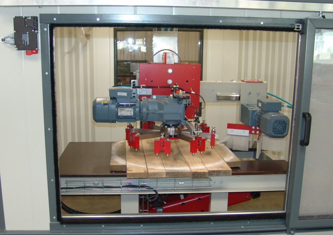
- A clamping plate with a diameter corresponding to the diameter of the barrel base to be produced.
- A turning device with claws, which is driven by a gear motor. This device is raised and lowered by a hydraulic cylinder.
- Tools: concave saw blade, which is adapted to the size of the barrel base to be produced and a cutting tool with carbide tip.
- The tools are mounted onto a spindle, which is driven by a motor. The shaft can be swiveled and is driven by a hydraulic cylinder.
- Adjustable stop, which limits the movement of the tool carrier.
- Adjusting spindle for adjusting the tool height and spindle and hand wheel for cross adjusting.
- An illuminated protective cabin over the machine
- Doors with electrical interlock for stopping the machine when the doors are opened
- Chip deflection sheet and extraction studs
- Turning plate with brushes for removing the chip
- Control panel with push button control
Working Method:
- The work piece to be processed is put onto a clamping plate, with a diameter corresponding to the diameter of the barrel base to be produced and is clamped with a turning device with claws.
- The turning device is driven by a gear motor.
- This device is raised and lowered by a hydraulic cylinder.
- The moves are controlled over a control panel.
- The clamping plate with the work piece is turned and the work piece is rounded and chamfered by a concave saw blade and a carbide tip tool.
Technical Data: BRX
| Barrel bases for barrel sizes | 225 to 700 liters | ||
|---|---|---|---|
| Material | Oak staves | 20 - 27 mm | thickness |
| Motors: | |||
| Tool motor | 11 kW | ||
| Gear motor for rotation of work piece | 0,55 kW | ||
| Gear motor brushes | 0.37 kW | ||
| Motor hydraulic unit | 3 kW | ||
| Total Installed power | 15 KW | ||
| Extraction for chip | one stud Ø 120 mm over protective cabin | ||
| Operating voltage | 480; 3; 60 | Volts; Phase; Cycles | others possible |
| Extraction data | Extraction studs | 2x Ø 140 mm | |
| Air speed | 30 m/s | ||
| Air consumption | 0.7 m³/s | 2.520 m³/h | |
| Vacuum in extraction line | 650 Pa | ||
| Height adjustment | 0,18 kW | ||
| Aggregate adjustment | 0,37 kW |
